More than 75% of hydraulic system failures trace back to one cause: contamination. For large production facilities, that single statistic translates into thousands of dollars in unplanned downtime, component replacement, and lost output. Understanding how hydraulic filtration works — and where it can fail — is the first step to preventing it.
This article covers the essentials: contamination types and sources, fluid cleanliness standards, filter media, housing selection, and where filters belong in your system.
Why Contamination Is the Primary Threat
Contamination compromises every function a hydraulic fluid is supposed to perform. A hydraulic fluid does four jobs: transmit energy, lubricate moving components, transfer heat, and maintain sealing. Contamination degrades all four.
The failure modes it triggers include:
- Orifice blockage
- Component wear and accelerated fatigue
- Oxidation of the fluid
- Additive breakdown
- Biological growth in the reservoir
None of these happen in isolation. Once contamination crosses a threshold, failure modes compound.
Contamination Types and Sources
Particulate Contamination
Particles split into two categories by size — and each causes a different type of damage. Silt (particles under 5 microns) causes gradual, cumulative wear that shortens component life over months. Larger particles above 5 microns cause sudden, acute failures — blocked valves, scored cylinder bores, seized pumps.
Both types matter. A system that passes on particle count but fails on silt distribution is already degrading.
Water Contamination
Free water above the fluid’s saturation level is aggressive. It emulsifies into the fluid, accelerates corrosion, changes viscosity behaviour, and breaks down additives. Even small amounts of free water — well below what looks like a problem — can shorten pump and valve life significantly.
Air Contamination
Dissolved air is generally harmless; free air is not. When system pressure drops, dissolved air comes out of solution and becomes free air. Free air causes oxidation and foaming, which disrupts flow consistency and can trigger pressure spikes.
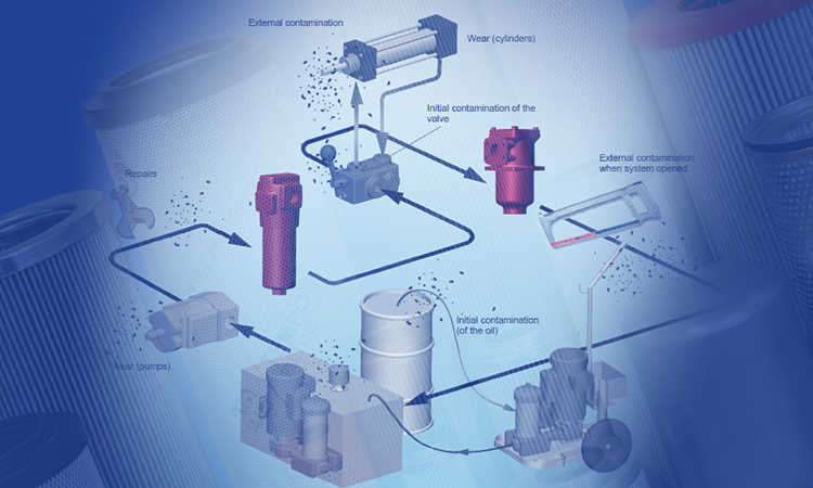
Where Contamination Enters
Three primary entry points:
- Manufacturing and assembly residue — metal particles, weld spatter, dirt left in lines during build
- System seal failures — external contamination entering through degraded seals or breathers
- Generated contamination — wear particles produced by components already in service
Fluid Cleanliness Standards: ISO 4406
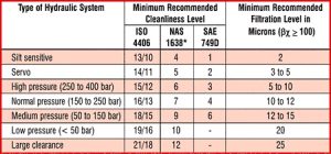
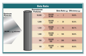
ISO 4406:1999 gives contamination a number — and that number determines whether your system is protected or exposed. The standard classifies particles at three size thresholds: 4, 6, and 14 microns. Each is assigned a range code. A typical cleanliness target might read 16/14/11 — three numbers representing particle count ranges at each threshold.
Component manufacturers specify the minimum cleanliness level required for their products. Operating below that level shortens service life proportionally. The target is not the same for every system: a servo valve requires far cleaner fluid than a cylinder.
Filter Media: Types and Selection
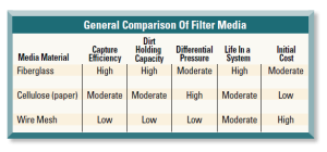
Surface vs. Depth Filtration
Surface filtration media trap particles on an external layer. Wire mesh falls into this category. It can be cleaned and reused, which makes it suitable for suction-side applications where accessibility is straightforward.
Depth filtration forces fluid through a tortuous internal path, capturing smaller particles throughout the media thickness. This approach handles finer filtration more effectively and is standard in pressure and return-line filters.
Materials
The three primary filter media materials are:
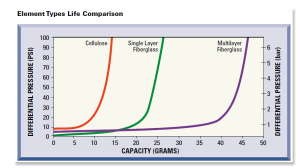
- Glass fibre (microglass) — captures fine particles efficiently, resists clogging longer, and outlasts cellulose in differential pressure curves
- Cellulose (paper) — lower cost, shorter service life, suitable where cleanliness targets are less demanding
- Wire mesh — cleanable, reusable, coarser filtration for suction protection
What Drives Selection
Selection is determined by four system variables: operating pressure, flow rate, fluid viscosity, and target ISO cleanliness level. As pressure increases, finer filtration is typically required. An efficient filter achieves the target cleanliness level in fewer passes — reducing the load on the system and extending element life.
Filter Element Life
Element life is read from two curves: differential pressure and dirt-holding capacity. As an element loads with captured contamination, differential pressure across it rises. When differential pressure hits the bypass valve threshold, the bypass opens — and unfiltered fluid moves through the system.
Glass fibre elements last longer than cellulose equivalents under equivalent contamination loads. The reason: they capture smaller particles more efficiently at lower differential pressure, and their structure resists early clogging that would otherwise trigger premature bypass.
Monitoring differential pressure — either via an indicator or continuous measurement — is the only reliable way to know when an element needs changing.
Filter Housing Selection
Housing design is defined by where in the circuit the filter sits. Each location has different pressure, flow, and contamination-load characteristics.
- Pressure-line housings must withstand full system pressure. They are rated for high burst strength and fatigue resistance.
- Return-line housings operate at lower pressure and handle the full flow returning to the reservoir. They are typically larger to accommodate flow volume with minimal pressure drop.
- Suction-line housings are designed to introduce the minimum possible restriction, since excessive suction restriction cavitates the pump.
Bypass valves are integral to housing design. They protect the housing and downstream components when a clogged element would otherwise block flow entirely. A bypass event is a warning — not normal operation.
Filter Types and Placement
Suction Filters
Suction filters protect the pump from coarse contamination in the reservoir. They use coarse elements — typically wire mesh — and are sized for minimal pressure drop. Over-specifying the element on a suction filter (choosing too fine a rating) can starve the pump and cause cavitation damage.
Pressure Filters
Pressure filters protect sensitive downstream components — servo valves, proportional valves, precision cylinders. They are positioned immediately after the pump outlet, before the fluid reaches any critical component. Element ratings are fine, typically matched to the cleanliness requirements of the most sensitive component in the circuit.
Return Filters
Return filters clean the entire fluid volume before it re-enters the reservoir. Every drop of fluid that has passed through actuators and valves goes through the return filter. This makes them the primary line of defence for system-wide contamination control.
Frequently Asked Questions
What is the most common cause of hydraulic system failure?
Contamination accounts for over 75% of hydraulic failures. Particulate contamination — both fine silt and larger particles — is the leading cause of component wear, valve blockage, and pump failure. Maintaining fluid cleanliness within the manufacturer’s specified ISO 4406 range is the most effective preventive measure.
How do I choose between glass fibre and cellulose filter media?
Glass fibre (microglass) elements outperform cellulose in most industrial hydraulic applications. They capture finer particles at lower differential pressure, resist clogging longer, and have a higher dirt-holding capacity. Cellulose elements suit lower-pressure systems where cleanliness targets are less stringent and cost is the primary constraint.
What does an ISO 4406 cleanliness code mean?
ISO 4406 classifies fluid contamination using three range codes — one each for particles at 4, 6, and 14 microns. Each code represents a particle count range per millilitre of fluid. For example, a code of 17/15/12 indicates progressively lower counts at each threshold. Component manufacturers publish the minimum code required for full service life.
When should I change a hydraulic filter element?
Change the element when the differential pressure indicator triggers — not on a calendar schedule alone. Differential pressure rises as the element loads with captured contamination. Waiting past the bypass trigger means unfiltered fluid is circulating. For critical systems, continuous differential pressure monitoring provides the earliest warning.
What happens if a hydraulic filter bypass valve opens?
The bypass valve opens when differential pressure across a clogged element reaches the valve’s set point. When it opens, fluid bypasses the filter element and enters the circuit unfiltered. This protects the housing from rupture, but contamination is no longer controlled. A bypass event requires immediate element replacement and a root-cause check on why the element loaded prematurely.
Conclusion
Hydraulic filtration is not a passive component category — it is the primary defence against the failure mode responsible for most hydraulic downtime. The right combination of media type, element rating, housing selection, and placement determines whether your system runs at target cleanliness or degrades under load. Get those four variables right, and contamination stops being a maintenance problem.
For filter selection support or technical specifications, contact the Tempo Filtre team.